A 15-year-old Air Handling Unit (AHU) with a clean, intact casing and solid structural integrity, these are often the first features noted during an initial site survey.
However, the internal equipment inside the unit is frequently overlooked. Components like belts, motors, bearings, and filter banks form complex subsystems that keep the AHU running efficiently. Over time, while the exterior remains in prime condition, these internal subsystems quietly drift away from their original design specification due to continuous mechanical wear and operational stress.
In this deep dive, we apply a systems engineering lens (T192) to the mechanical dynamics inside an AHU, focusing on mechanical power transmission, internal performance drift, and how EC fan retrofits can redefine the operational baseline.
⚙️ The Mechanics: How the Subsystems Interact
Air Handling Units can be configured in several ways, but two of the most common setups interact as follows:
Belt Drive System - A traditional setup where the motor is physically separated from the fan. Rotational power is transferred via a belt connecting pulleys on both the motor and fan shaft. This configuration requires regular maintenance due to belt wear, bearing fatigue, tension drop, and belt slippage.

FIG 01 // Example diagram of a Belt Drive System
Direct Drive System - A modern approach that eliminates several mechanical moving parts. The fan impeller is mounted directly onto the motor shaft, reducing failure points and eliminating belt-related maintenance entirely.

FIG 02 // Example diagram of a Direct Drive System
-
The Motor (Electrical to Mechanical):
The motor converts electrical energy into rotational mechanical (kinetic) energy at the motor shaft. In modern or retrofitted systems, motor speed is modulated using a Variable Frequency Drive (VFD), a type of Variable Speed Drive (VSD) that adjusts frequency and voltage to match real-time airflow demand.
-
The Pulley & Belt Transmission:
In a traditional belt-driven system, the pulley on the motor and the pulley on the fan shaft are often different sizes. This relationship is defined by the pitch ratio. By varying the relative diameters of the drive and driven pulleys, engineers can establish the required fan speed () relative to the motor’s operational output.
-
The Bearings & Fan Shaft:
The bearings supporting the fan shaft are subjected to two primary mechanical forces: radial loads (perpendicular forces from the rotating impeller and belt tension) and axial loads (parallel forces caused by air resistance against the blades). Regular lubrication and alignment ensure these loads are distributed evenly while keeping frictional heat to a minimum.
-
The Impeller (Mechanical to Fluid Dynamic):
The fan impeller converts rotational mechanical energy into fluid dynamic energy, specifically kinetic energy (air velocity) and potential energy (static pressure). The overall air volume moved through the ductwork by this process is measured as volumetric airflow rate (), typically expressed in .
📉 The Design Spec vs. Reality: Identifying Hidden Performance Drift
During the design phase every component within an AHU is selected to deliver a specific volumetric airflow specific to the environment and what the facility or space Is used for. Over 15-20 years of continuous operation multiple factors can cause the unit to drift from its original state at commissioning.
-
Frictional Losses & Belt Slippage:
Over time, belt stretch and pulley wear lead to belt slippage. Every 1% increase in belt slip results in a direct 1% reduction in fan speed (RPM). Because airflow (Q) is directly proportional to fan speed, higher slip equals lower speed and reduced air volume, ultimately causing the AHU to fall short of its required Air Changes per Hour (ACH).
-
Bearing Wear & Dynamic Unbalance:
Micro-vibrations caused by an unbalanced impeller or internal air turbulence produce microscopic oscillations across the shaft bearings. This movement repeatedly disrupts and squeezes out the thin protective oil film, causing metal-on-metal friction. Over time, this drastically increases mechanical resistance, accelerates bearing damage, and wastes energy as heat and vibration.
-
Internal Resistance (Coils & Filters):
Accumulating matter on heating/cooling coils increases internal pressure drop. To maintain design airflow against this resistance, the fan must draw more power. If it can’t, airflow drops below specification, compromising indoor air quality (IAQ).
⚡ Legacy Belt-Driven vs. Direct-Drive EC Fans
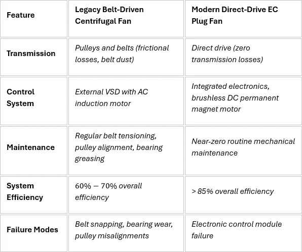
FIG 03 // Table of comparison for Belt Driven and Direct Drive
Retrofitting an existing, structurally sound casing with an EC fan array eliminates mechanical transmission losses, restores design airflow, and significantly reduces ongoing reactive maintenance hours.
🏛️ The Consultant’s View: System-Level Lifecycle Analysis
Evaluating ventilation plant properly means looking past the metal casing and into the mechanical assembly. Strategic asset management isn’t about judging an asset by how clean it looks; it’s about understanding how component-level wear degrades whole-system performance over time. This approach allows us to guide clients away from superficial assumptions and toward data-driven capital planning.
💬 Over to You:
When reviewing central HVAC plant, how do you balance whole-unit replacement against targeted component retrofits like EC fan upgrades?